In physics, the topic of parallel and series connection is studied, and it can be not only conductors, but also capacitors. It is important here not to get confused about how each of them looks on the diagram. And only then apply specific formulas. By the way, you need to remember them by heart.
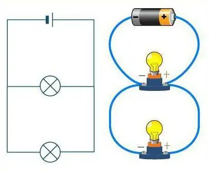
How to distinguish between these two compounds?
Take a close look at the diagram. If you imagine the wires as a road, then the cars on it will play the role of resistors. On a straight road without any branching, cars drive one after the other, in a chain. The series connection of conductors also looks the same. The road in this case can have an unlimited number of turns, but not a single intersection. No matter how the road (wires) wagged, the machines (resistors) will always be located one after another, in one chain.
It's quite a different matter if a parallel connection is considered. Then the resistors can be compared with athletes at the start. They areeach stand on its own track, but they have the same direction of movement, and the finish line is in the same place. Similarly, resistors - each of them has its own wire, but they are all connected at some point.
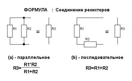
Formulas for current strength
It is always discussed in the topic "Electricity". Parallel and series connections affect the amount of current in resistors in different ways. For them, formulas are derived that can be remembered. But it's enough just to remember the meaning that is invested in them.
So, the current in series connection of conductors is always the same. That is, in each of them the value of the current strength is not different. You can draw an analogy if you compare a wire with a pipe. In it, water always flows the same way. And all obstacles in its path will be swept away with the same force. Same with current. Therefore, the formula for the total current in a circuit with a series connection of resistors looks like this:
I gen=I 1=I 2
Here, the letter I denotes the strength of the current. This is a common notation, so you need to remember it.
The current in parallel connection will no longer be a constant value. With the same analogy with a pipe, it turns out that the water will be divided into two streams if the main pipe has a branch. The same phenomenon is observed with current when a branching of wires appears in its path. The formula for the total current strength when the conductors are connected in parallel:
I gen=I 1 + I 2
If the branching is made up of wires thatmore than two, then in the above formula there will be more terms by the same number.
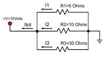
Formulas for stress
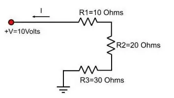
When a circuit is considered in which the conductors are connected in series, the voltage in the entire section is determined by the sum of these values on each specific resistor. You can compare this situation with plates. It will be easy for one person to hold one of them, he will also be able to take the second one nearby, but with difficulty. One person will no longer be able to hold three plates next to each other, the help of a second will be required. Etc. People's efforts add up.
The formula for the total voltage of a section of a circuit with a series connection of conductors looks like this:
U gen=U 1 + U 2, where U is the designation adopted for electrical voltage.
Another situation arises if a parallel connection of resistors is considered. When plates are stacked on top of each other, they can still be held by one person. So you don't have to add anything. The same analogy is observed when the conductors are connected in parallel. The voltage on each of them is the same and equal to that which is on all of them at once. The formula for total voltage is:
U gen=U 1=U 2
Formulas for electrical resistance
You can no longer memorize them, but know the formula of Ohm's law and derive the desired one from it. It follows from this law thatvoltage is equal to the product of current and resistance. That is, U=IR, where R is the resistance.
Then the formula you will need to work with depends on how the conductors are connected:
- in series, so you need equality for voltage - IgenRtotal=I1 R1 + I2R2;
- in parallel, it is necessary to use the formula for the current strength - Utotal / Rtotal=U1/ R1 + U2 / R2.
Followed by simple transformations, which are based on the fact that in the first equality all the currents have the same value, and in the second - the voltages are equal. So they can be shortened. That is, the following expressions are obtained:
- R gen=R 1 + R 2 (for series connection of conductors).
- 1 / R gen=1 / R 1 + 1 / R 2(when connected in parallel).
When the number of resistors connected to the network increases, the number of terms in these expressions changes.
It is worth noting that parallel and series connection of conductors have different effects on the total resistance. The first of them reduces the resistance of the circuit section. Moreover, it turns out to be less than the smallest of the resistors used. When connected in series, everything is logical: the values add up, so the total number will always be the largest.
Work current
The previous three quantities make up the laws of parallel connection and series arrangement of conductors in a circuit. Therefore, it is imperative to know them. About work and power, you just need to remember the basic formula. It is written as follows: A \u003d IUt, where A is the work of the current, t is the time of its passage through the conductor.
In order to determine the total work with a serial connection, you need to replace the voltage in the original expression. You get the equality: A \u003d I(U 1 + U 2)t, opening the brackets in which it turns out that the work on the entire section is equal to them amount on each specific current consumer.
The reasoning proceeds similarly if a parallel connection scheme is considered. Only the current strength is supposed to be replaced. But the result will be the same: A=A 1 + A 2.
Current power
When deriving a formula for power (notation "P") of a circuit section, you again need to use one formula: P \u003d UI. After such reasoning, it turns out that parallel and series connections are described by such a formula for power: P \u003d P1 + P 2.
That is, no matter how the schemes are drawn up, the total power will be the sum of those involved in the work. This explains the fact that it is impossible to include many powerful devices in the apartment network at the same time. She just can't take the load.
How does the connection of conductors affect the repair of the New Year's garland?
Immediately after one of the bulbs burns out, it becomes clear how they were connected. Atserial connection, none of them will light up. This is due to the fact that a lamp that has become unusable creates a break in the circuit. Therefore, you need to check everything to determine which one is burned out, replace it - and the garland will start working.
If it uses a parallel connection, then it does not stop working if one of the bulbs fails. After all, the chain will not be completely broken, but only one parallel part. To repair such a garland, you do not need to check all the elements of the circuit, but only those that do not glow.

What happens to a circuit if capacitors are included instead of resistors?
When they are connected in series, the following situation is observed: charges from the pluses of the power source come only to the outer plates of the extreme capacitors. Those in between simply pass that charge along the chain. This explains the fact that the same charges appear on all the plates, but with different signs. Therefore, the electric charge of each capacitor connected in series can be written as follows:
q gen =q 1=q 2.
In order to determine the voltage on each capacitor, you will need to know the formula: U=q / C. In it, C is the capacitance of the capacitor.
Total voltage follows the same law as resistors. Therefore, replacing the voltage in the capacitance formula with the sum, we get that the total capacitance of the devices must be calculated using the formula:
C=q / (U 1 + U2).
You can simplify this formula by flipping the fractions and replacing the ratio of voltage to charge with capacitance. It turns out the following equality: 1 / С=1 / С 1 + 1 / С 2.
The situation looks somewhat different when the capacitors are connected in parallel. Then the total charge is determined by the sum of all charges that accumulate on the plates of all devices. And the voltage value is still determined according to general laws. Therefore, the formula for the total capacitance of capacitors connected in parallel is:
С=(q 1 + q 2) / U.
That is, this value is considered as the sum of each of the devices used in the connection:
S=S 1 + S 2.
How to determine the total resistance of an arbitrary connection of conductors?
That is, one in which successive sections replace parallel ones, and vice versa. For them, all the described laws are still valid. Only you need to apply them in stages.
First, it is supposed to mentally expand the scheme. If it is difficult to imagine it, then you need to draw what happens. The explanation will become clearer if we consider it with a specific example (see figure).
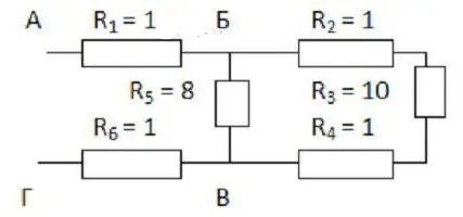
It is convenient to start drawing from points B and C. They must be placed at some distance from each other and from the edges of the sheet. On the left, one wire approaches point B, and two are already directed to the right. Point B, on the other hand, has two branches on the left, and one wire after it.
Now you need to fill the space between thesedots. Three resistors with coefficients of 2, 3 and 4 should be placed along the top wire, and the one with an index of 5 will go from the bottom. The first three are connected in series. With the fifth resistor they are in parallel.
The remaining two resistors (the first and sixth) are connected in series with the considered section of the BV. Therefore, the drawing can simply be supplemented with two rectangles on either side of the selected points. It remains to apply the formulas for calculating the resistance:
- first the one given for serial connection;
- then for parallel;
- and again for consecutive.
In this way, you can deploy any, even very complex scheme.
The problem of serial connection of conductors
Condition. Two lamps and a resistor are connected in a circuit one behind the other. The total voltage is 110 V and the current is 12 A. What is the value of the resistor if each lamp is rated at 40 V?
Decision. Since a series connection is being considered, the formulas for its laws are known. You just need to apply them correctly. Start by finding out the voltage value across the resistor. To do this, you need to subtract two times the voltage of one lamp from the total. It turns out 30 V.
Now that two quantities are known, U and I (the second of them is given in the condition, since the total current is equal to the current in each series consumer), we can calculate the resistance of the resistor using Ohm's law. It turns out to be 2.5 ohms.
Answer. The resistance of the resistor is 2.5 ohms.
Taskfor connection of capacitors, parallel and series
Condition. There are three capacitors with capacities of 20, 25 and 30 microfarads. Determine their total capacitance when connected in series and parallel.
Decision. It's easier to start with a parallel connection. In this situation, all three values just need to be added. Thus, the total capacitance is 75uF.
The calculations will be somewhat more complicated when these capacitors are connected in series. After all, first you need to find the ratio of unity to each of these capacities, and then add them to each other. It turns out that the unit divided by the total capacity is 37/300. Then the desired value is approximately 8 microfarads.
Answer. The total capacitance in series connection is 8 uF, in parallel - 75 uF.


