After the installation of the pipeline is completed, it is further tested for strength and tightness. A hydraulic or pneumatic method can be used, sometimes they are used in combination. Such a check is necessary in accordance with the requirements of sanitary norms and rules.
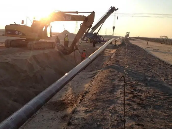
Preparatory work before hydraulic strength testing of pipelines
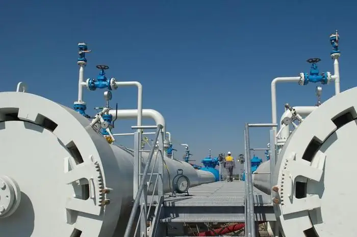
Before carrying out hydraulic tests, careful preparatory work should be carried out. To do this, the design is divided into divisions, then its external inspection is carried out. The next step is to check the technical documentation. Drain valves are fixed to divisions, air valves and plugs are connected to them. A temporary pipeline line is installed from the pressing and filling devices. The tested section is disconnected from the remaining divisions of the pipe; for this, plugs with shanks are used.
Equipment and apparatus must also be disconnected. To do this, use a complex shut-offwire fittings are unacceptable. The strength test involves connecting the pipeline to hydraulics, among such devices should be highlighted:
- overhead networks;
- pump stations;
- compressors.
All this allows you to provide the pressure you need for testing. Tests must be carried out under the guidance of a foreman or manufacturer, taking into account the requirements of technical documentation, design papers and instructions. It is important to comply with safety precautions and the regulations of state technical supervision.
For reference
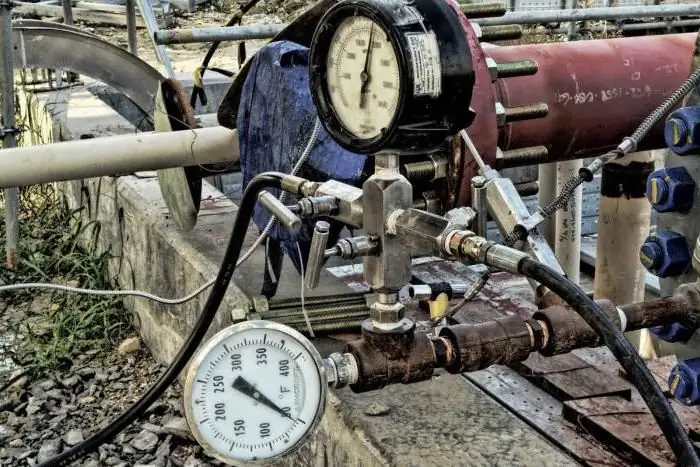
Strength testing involves the use of test fixtures and pressure gauges. They must first pass an expert check, be sure to be sealed. Pressure gauges must be of an accuracy class, the minimum level of which is kept within 1.5, which complies with state standards 2405-63. Case diameter should be 1.5 cm or more. The thermometers used must have scales up to 0.1 °C.
Work methodology
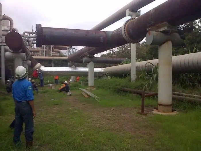
Hydraulic strength test is also carried out to determine the density. During test experiments, the pressure value is set in accordance with the design documentation in kgf/cm2. With regard to steel structures, their operating threshold should not exceed 4 kgf/cm2, when the operating temperature of the system exceeds 400 °C. The pressure value at the same timewill be equal to the limit from 1.5 to 2.
If the working threshold of the steel structure exceeds 5 kgf/cm2, then the pressure value will be 1.25. Sometimes this value is determined by a formula that assumes the sum of the working load and the value 3 kgf/cm2. If we are talking about products made of cast iron or polyethylene, then the pressure value will be equal to 2 or more. As for non-ferrous metal alloys, the figure is equal to one. To obtain the desired loads, the following types of presses are used:
- operational;
- drive gear;
- mobile plunger;
- manual (piston);
- hydraulic.
Testing
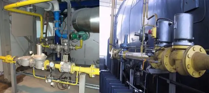
Testing the strength and tightness of the hydraulic method is carried out in several stages. At the first, a press or a hydraulic pump is connected. Next, the brigade installs pressure gauges, and the structure itself is filled with water. It is important to ensure that air is expelled from the system; for this, the air vents are left open. If water got into them, it means that there is no air left.
Once the system is completely filled with liquid, its surface should be inspected for cracks, leaks and flaws that may occur around the perimeter in the connecting elements. The strength and tightness test at the next stage involves the supply of pressure with its prolonged exposure. The load can be gradually reduced until the indicative values reach the standard level. This isallows you to re-examine the state of the system. The pipeline at the next stage is freed from water, and the equipment can be disconnected and removed.
Secondary inspection and final work
If there are glass joints in the system, then they must be subjected to loads for 20 minutes, but for other materials, 5 minutes will be enough. During the secondary inspection, attention should be paid to adhesions and welds. They should be tapped with a hammer weighing 1.5 kg or less. It is important to ensure access within 20 mm.
When testing non-ferrous metal parts, use a wooden mallet, the weight of which does not exceed 0.8 kg. Other materials are not subjected to such tapping, as they can be damaged. The hydraulic strength test is considered successful if the pressure gauge showed no pressure drop, no leaks were detected, and the welds and flanged connections worked stably, withstanding the load.
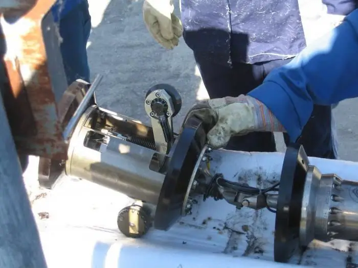
Check should be repeated if the results were unsatisfactory, but work should be carried out only after all errors have been eliminated. For hydraulic tests (at low temperatures), substances can be added to the liquid that reduce the crystallization temperature of water. The liquid can be heated, and the pipes can be additionally insulated.
Pneumatic tests
Considering the strength testing methods, it is necessary to highlight the pneumatictesting. It is used to test strength and/or density. Freon and ammonia products are not hydraulically tested, in this case only pneumatic testing is used.
Sometimes it happens that hydraulic studies cannot be applied. This can happen when the air temperature drops below zero or there is no water in the area. If there is a directive to use air or inert gases, then hydraulic testing cannot be applied.
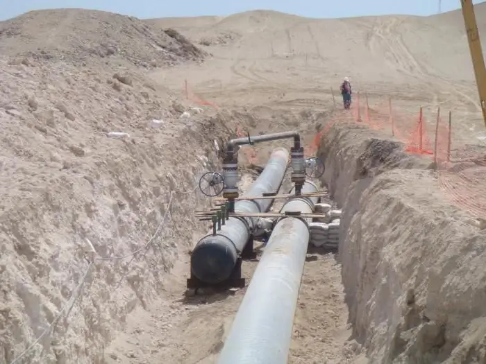
Pneumatic testing should also be used when there is high stress in the supporting structures and pipelines due to the impressive mass of water. For the implementation of such tests, an inert gas or air is used. Mobile compressors or a compressed air network should be used.
Tests for strength and density require compliance with the pressure and the length of the divisions. Thus, if the diameter is 2 cm, then the pressure should be equal to 20 kgf/cm2. If the diameter varies from 2 to 5, then the pressure should be 12 kgf/cm2. When the diameter exceeds 5cm, the pressure should be 6kgf/cm2. If the project requires it, other values can be used.
Useful information
Above-ground structures made of glass and cast iron do not pass pneumatic tests. If the steel system has cast iron fittings, then inert gas or air can be used for testing, as an exception, ductile parts arecast iron.
Procedure of work
Pneumatic strength testing involves filling the pipeline with air or gas at the first stage. Then the pressure rises. When the level rises to 0.6, you can proceed to the inspection of the area being checked. This is true for structures where the working pressure index reaches 2 kgf/cm2.
During the inspection, the load must be increased. However, tapping with a hammer those surfaces that are under load is unacceptable. At the final stage, the system is inspected under workloads. Testing the tensile strength of welded joints and seams, flanges and glands involves the application of a soapy solution.
If the system transports flammable, poisonous, toxic substances, the leak test is supplemented by a tightness test. To do this, the pressure drop is studied in parallel. It is important to check all equipment that is connected to the system. If, during the strength test, the pressure on the pressure gauge did not decrease, and sweating and leakage were not detected in the glands and connecting seams, then the result is considered satisfactory.
Information about test reports
When testing is carried out by a construction organization or commission, the following documentation is submitted:
- executive scheme;
- test site design;
- welding journal;
- journal of insulation works;
- testing act for strength and tightness.
As an additional application arecertificates for parts and pipes, as well as passports for equipment. The result of testing a separate section is an act.
Based on the results of the investigation of the leak, the commission draws up an act, materials are attached to it, which should contain:
- organization name;
- Commission composition;
- test parameters details;
- certificate for a collapsed (defective) pipe;
- information about the design of the pipeline;
- an extract from the welding journal;
- altitude mark of the gap;
- act of production and acceptance of construction and installation works.
The act of testing the pipeline for strength is drawn up taking into account the current regulations. It necessarily implies an indication of the composition of the commission, the timing of the work and the conclusion, the signatures of the responsible persons. From these documents it will be possible to find out at what parameters the tightness test was carried out. This should include not only pressure, but also the total length of the system. The act of testing pipelines for strength will contain the name of the devices used, other equipment, as well as the places of their installation and the length of the section from which water was removed after the test.
Conclusion
Testing of pipelines and evaluation of the results must be carried out exclusively by qualified personnel. They must receive job descriptions and have the appropriate skills. It is important to remember that testing the pipeline for strength and tightness should be carried out in a timely and thorough manner, because this is the only wayit will be possible to exclude accidents, losses and even accidents.


