Aerodynamic drag is a force acting opposite to the relative motion of any object. It can exist between two layers of solid surface. Unlike other resistive sets, such as dry friction, which are almost independent of speed, the drag forces obey a given value. Although the ultimate cause of the action is viscous friction, turbulence is independent of it. The drag force is proportional to the laminar flow velocity.
Concept
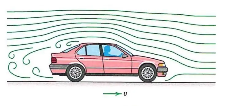
Aerodynamic drag is the force that acts on any moving solid body in the direction of the oncoming fluid. In terms of the near field approximation, drag is the result of forces due to the distribution of pressure over the surface of the object, symbolized by D. Due to skin friction, which is the result of viscosity, is denoted De. Alternatively, calculated from the point of view of the flow field, the forceresistance arises as a result of three natural phenomena: shock waves, vortex layer and viscosity. All this can be found in the table of aerodynamic drag.
Overview
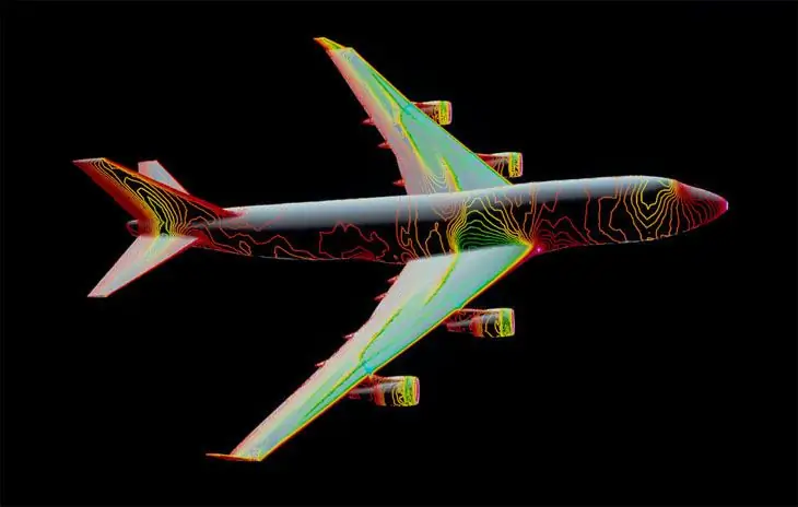
The distribution of pressure acting on the surface of a body affects large forces. They, in turn, can be summed up. The downstream components of this value constitute the drag power, Drp, due to the distribution of pressure that affects the body. The nature of these forces combines shock wave effects, vortex system generation and wake mechanisms.
The viscosity of a fluid has a significant effect on drag. In the absence of this component, the pressure forces acting to slow the vehicle are neutralized by the power that is in the aft part and pushes the vehicle forward. This is called repressurization, resulting in zero aerodynamic drag. That is, the work that the body does on the airflow is reversible and recoverable as there are no frictional effects to convert the energy of the flow into heat.
Pressure recovery works even in case of viscous movement. This value, however, results in power. It is the dominant component of drag in the case of vehicles with areas of divided flow, in which head recovery is considered rather inefficient.
The force of friction, which is the tangential power on the surfaceaircraft, depends on the configuration of the boundary layer and the viscosity. Aerodynamic drag, Df, is calculated as the downstream projection of bog sets estimated from the body surface.
The sum of friction and pressure resistance is called viscous resistance. From a thermodynamic perspective, quagmire effects are irreversible phenomena and hence they create entropy. The calculated viscous resistance Dv uses changes in this value to accurately predict the rebound force.
Here it is also necessary to give the formula for air density for gas: РV=m/MRT.
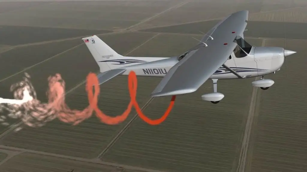
When an aircraft produces lift, there is another component of pushback. Induced resistance, Di. It arises from the change in the pressure distribution of the vortex system that accompanies the production of the elevator. An alternative lift perspective is achieved by considering the change in momentum of the airflow. The wing intercepts the air and forces it to move down. This results in an equal and opposite drag force acting on the wing, which is lift.
Changing the momentum of the air flow down leads to a decrease in the reverse value. That it is the result of the force acting forward on the applied wing. An equal but opposite mass acts on the back, which is the induced drag. It tends to be the most important component for aircraft during takeoff or landing. Another drag object, wave drag (Dw) is due to shock wavesat transonic and supersonic speeds of flight mechanics. These rolls cause changes in the boundary layer and pressure distribution over the surface of the body.
History
The idea that a moving body passing through air (density formula) or other liquid encounters resistance has been known since the time of Aristotle. An article by Louis Charles Breguet written in 1922 began an effort to reduce drag through optimization. The author continued to bring his ideas to life, creating several record-breaking aircraft in the 1920s and 1930s. Ludwig Prandtl's boundary layer theory in 1920 provided an incentive to minimize friction.
Another important call for sequencing was made by Sir Melville Jones, who introduced theoretical concepts to convincingly demonstrate the importance of sequencing in aircraft design. In 1929, his work The Streamlined Airplane presented to the Royal Aeronautical Society was seminal. He proposed an ideal aircraft that would have minimal drag, leading to the concept of a "clean" monoplane and retractable undercarriage.
One of the aspects of Jones's work that most shocked the designers of the time was his plot of horse power versus speed for a real and ideal plane. If you look at the data point for the aircraft and extrapolate it horizontally to a perfect curve, you can see the payoff for the same power. When Jones had finished his presentation, one of the listenerslevel of importance as the Carnot cycle in thermodynamics.
Lift-induced resistance
The lift-induced backlash results from the creation of a slope on a three-dimensional body such as an aircraft wing or fuselage. Induced braking consists mainly of two components:
- Drag due to creating trailing vortices.
- Having additional viscous drag that is not there when lift is zero.
The back vortices in the flow field present as a result of the lifting of the body are due to the turbulent mixing of air above and below the object, which flows in several different directions as a result of the creation of lift.
With other parameters that remain the same as the lift created by the body, the resistance caused by the slope also increases. This means that with an increase in the angle of attack of the wing, the lift coefficient increases, as does the rebound. At the start of a stall, the prone aerodynamic force decreases dramatically, as does the lift-induced drag. But this value increases due to the formation of a turbulent unattached flow after the body.
Spurious drag
This is the resistance caused by moving a solid object through a liquid. Parasitic drag has several components, including movement due to viscous pressure and due to surface roughness (skin friction). In addition, the presence of several bodies in relative proximity can cause the so-calledinterference resistance, which is sometimes described as a component of the term.
In aviation, induced backlash tends to be stronger at lower speeds because a high angle of attack is required to maintain lift. However, as the speed increases, it can be reduced, as well as the induced drag. Parasitic drag, however, becomes greater because the fluid flows faster around protruding objects, increasing friction.
At higher speeds (transonic), wave drag reaches a new level. Each of these forms of repulse varies proportionally to the others depending on the speed. So the overall drag curve shows a minimum at some airspeed - the aircraft will be at or near optimum efficiency. Pilots will use this speed to maximize endurance (minimum fuel consumption) or glide distance in the event of an engine failure.
Aviation Power Curve
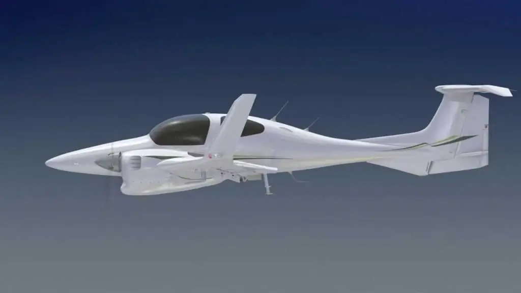
The interaction of parasitic and induced drag as a function of airspeed can be represented as a characteristic line. In aviation, this is often referred to as the power curve. It is important to pilots because it shows that below a certain airspeed, and counterintuitively, more thrust is required to maintain it as the airspeed decreases, not less. The implications of being "behind the scenes" in flight are important and are taught as part of pilot training. On subsonicairspeeds where the U-shape of this curve is significant, wave drag has not yet become a factor. That is why it is not shown on the curve.
Braking in transonic and supersonic flow
Compressive wave drag is the drag that is created when a body moves through a compressible fluid and at speeds close to the speed of sound in water. In aerodynamics, wave drag has many components depending on the driving mode.
In transonic flight aerodynamics, wave drag is the result of the formation of shock waves in the liquid, which are formed when creating local areas of supersonic flow. In practice, such a motion occurs on bodies moving well below the speed of the signal, since the local speed of the air increases. However, full supersonic flow over the vehicle will not develop until the value has gone much further. Aircraft flying at transonic speeds often experience wave conditions during the normal course of flight. In transonic flight, this repulsion is commonly referred to as transonic compressibility drag. It greatly intensifies as its flight speed increases, dominating other forms at those speeds.
In supersonic flight, wave drag is the result of shock waves present in the fluid and attached to the body, forming at the leading and trailing edges of the body. In supersonic flows, or in hulls with sufficiently large angles of rotation, there will instead beloose shock or curved waves are formed. In addition, local regions of transonic flow may occur at lower supersonic speeds. Sometimes they lead to the development of additional shock waves present on the surfaces of other lift bodies, similar to those found in transonic flows. In powerful flow regimes, wave resistance is usually divided into two components:
- Supersonic lift depending on value.
- Volume, which also depends on the concept.
The closed-form solution for the minimum wave resistance of a body of revolution with a fixed length was found by Sears and Haack and is known as the "Seers-Haack Distribution". Similarly, for a fixed volume, the form for the minimum wave resistance is "Von Karman Ogive".
Busemann's biplane, in principle, is not subject to such action at all when operating at design speed, but is also not capable of generating lift.
Products

A wind tunnel is a tool used in research to study the effect of air moving past solid objects. This design consists of a tubular passage with the object under test placed in the middle. Air is moved past the object by a powerful fan system or other means. The test object, often referred to as a pipe model, is equipped with appropriate sensors to measure air forces, pressure distribution, or otheraerodynamic characteristics. This is also necessary in order to notice and correct the problem in the system in time.
What are the types of aircraft
Let's look at history first. The earliest wind tunnels were invented at the end of the 19th century, in the early days of aviation research. It was then that many tried to develop successful heavier-than-air aircraft. The wind tunnel was conceived as a means of reversing the conventional paradigm. Instead of standing still and moving an object through it, the same effect would be obtained if the object stood still and the air moved at a higher speed. In this way, a stationary observer can study the flying product in action and measure the practical aerodynamics imposed on it.
The development of pipes accompanied the development of the aircraft. Large aerodynamic items were built during World War II. Testing in such a tube was considered strategically important during the development of supersonic aircraft and missiles during the Cold War. Today, aircraft are anything. And almost all the most important developments have already been introduced into everyday life.
Later wind tunnel research became a matter of course. The effect of wind on man-made structures or objects had to be studied when buildings became tall enough to present large surfaces to the wind, and the resulting forces had to be resisted by the internal elements of the building. The definition of such sets was required before building codes coulddetermine the required strength of structures. And such tests continue to be used for large or unusual buildings to this day.
Even later, checks were applied to the aerodynamic drag of cars. But this was not to determine the forces as such, but to establish ways to reduce the power required to move the car along the roadbeds at a given speed. In these studies, the interaction between road and vehicle plays a significant role. It is he who must be taken into account when interpreting test results.
In a real situation, the roadway moves relative to the vehicle, but the air is still relative to the road. But in a wind tunnel, the air moves relative to the road. While the latter is stationary relative to the vehicle. Some test vehicle wind tunnels include moving belts under the test vehicle. This is to get closer to the actual state. Similar devices are used in wind tunnel takeoff and landing configurations.
Equipment
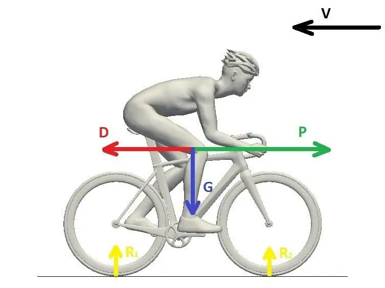
Samples of sports equipment have also been common for many years. They included golf clubs and balls, Olympic bobsleds and cyclists, and racing car helmets. The aerodynamics of the latter is especially important in vehicles with an open cab (Indycar, Formula One). Excessive lifting force on the helmet can cause significant stresson the neck of the driver, and the separation of the flow on the rear side is a turbulent seal and, as a result, impaired vision at high speeds.
Advances in computational fluid dynamics (CFD) simulations on high-speed digital computers have reduced the need for wind tunnel testing. However CFD results are still not completely reliable, this tool is used to verify CFD predictions.


