Perhaps the main aircraft unit is the wing. It is the wing that creates lift that keeps a multi-ton aircraft in the air, preventing it from falling. It is no coincidence that designers have an expression that the one who owns the wing also controls the aircraft. The pursuit of improving the aerodynamic characteristics of aircraft forces developers to constantly improve the wing, working on its shape, weight and profile.
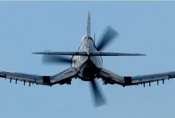
Wing in profile
Aircraft wing profile is a geometric section of the wing running parallel to the aircraft axis. Or more simply - a side view of the wing. Over the long years of the development of the aircraft industry, various laboratories and institutes have constantly developed and tested wings of various configurations. Speeds grew, the mass of aircraft, tasks changed - and all this required new wing profiles.
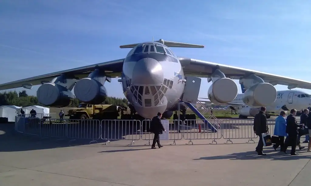
Profile types
Today, there are various wing profiles,different in purpose. The same type can have many variants and be used on different aircraft. But in general, the existing main types of profiles can be illustrated by the image below.
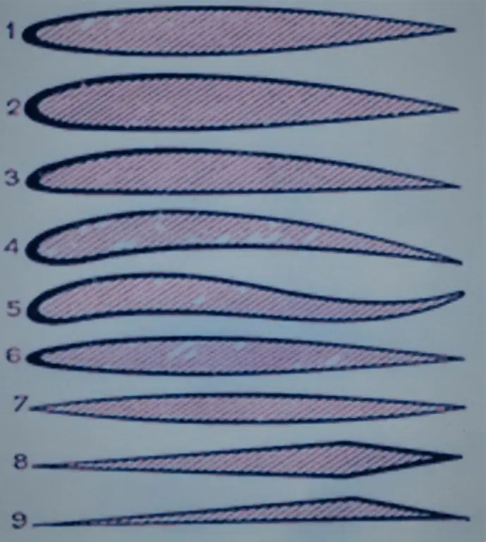
- Symmetrical.
- Asymmetrical.
- Plano-convex.
- Binconvex.
- S-shaped.
- Laminated.
- Lenticular.
- Diamond-shaped.
- Wedge-shaped.
On some aircraft, a variable profile is used along the length of the wing, but usually its shape is unchanged throughout.
Geometry
Externally, the profile of the wing resembles a worm or something like that. Being a complex geometric figure, it has its own set of characteristics.
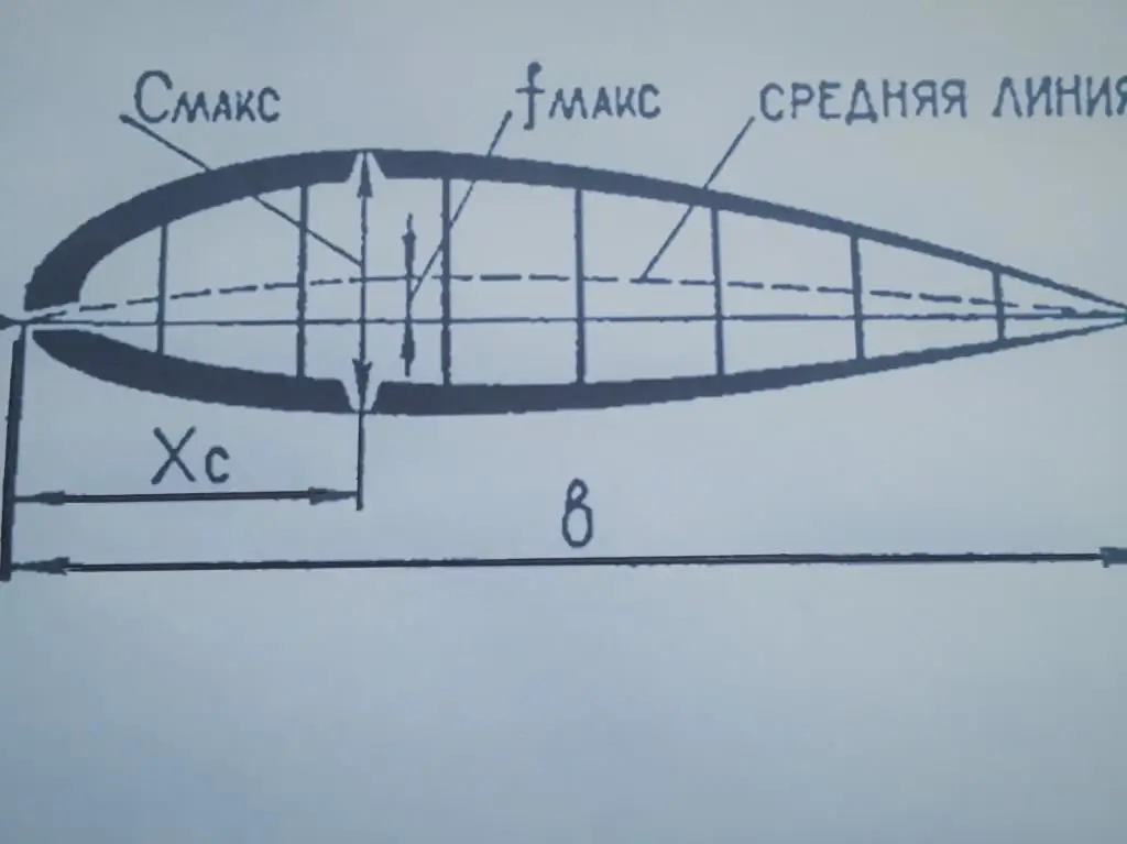
The figure shows the main geometric characteristics of the aircraft wing profile. The distance (b) is called the wing chord and is the distance between the extreme points in front and behind. The relative thickness is determined by the ratio of the maximum profile thickness (Cmax) to its chord and is expressed as a percentage. The maximum thickness coordinate is the ratio of the distance from the toe to the place of maximum thickness (Xc) to the chord (b) and is also expressed as a percentage. The center line is a conditional curve equidistant from the upper and lower wing panels, and the deflection arrow (fmax) is the maximum distance from the chord of the center line. Another indicator - relative curvature - is calculated by dividing (fmax) by a chord (b). Traditionally, all these values are expressed as a percentage. In addition to those already mentioned, there is the radius of the profile nose, the coordinates of the greatest concavity, and a number of others. Each profile has its own code and, as a rule, the main geometric characteristics are present in this code.
For example, profile B6358 has a profile thickness of 6%, a concavity arrow position of 35%, and a relative curvature of 8%. The notation system, unfortunately, is not unified, and different developers use ciphers in their own way.
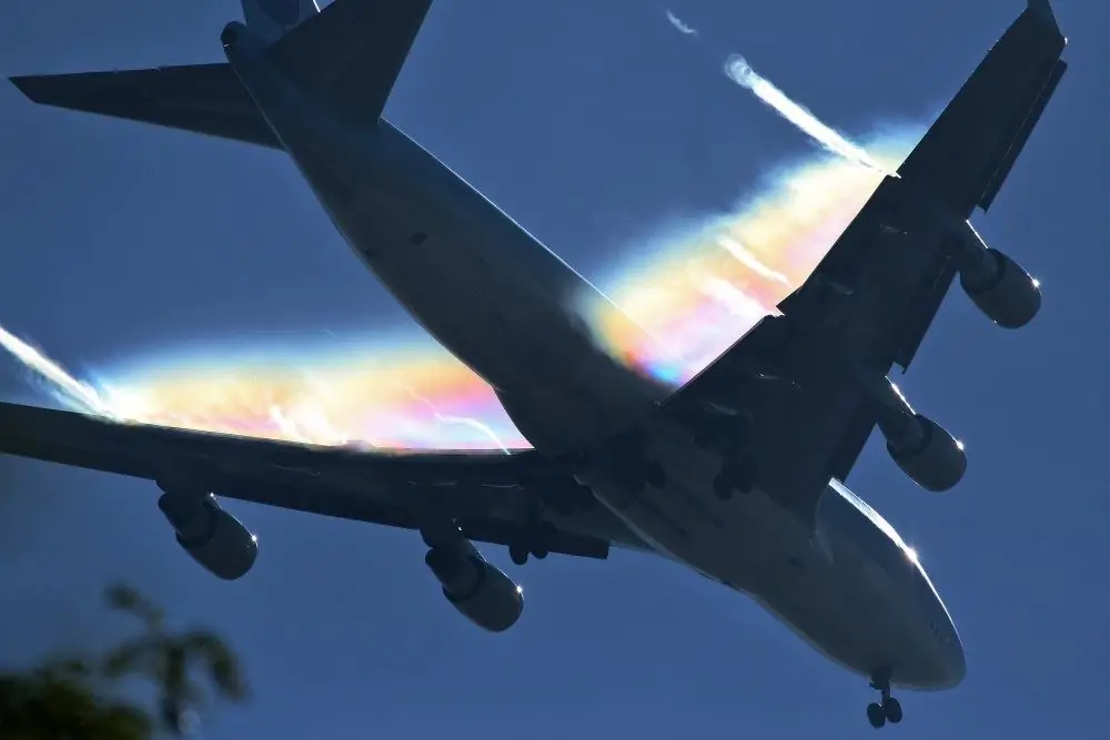
Aerodynamics
Fancy, at first glance, drawings of wing sections are made not out of love for high art, but solely for pragmatic purposes - to ensure high aerodynamic characteristics of wing profiles. These most important characteristics include the lift coefficient Su and the drag coefficient Cx for each specific airfoil. The coefficients themselves do not have a constant value and depend on the angle of attack, speed and some other characteristics. After testing in a wind tunnel, a so-called polar can be drawn up for each profile of an aircraft wing. It reflects the relationship between Cx and Su at a certain angle of attack. Special handbooks have been created containing detailed information about each aerodynamic profile of the wing and illustrated with appropriate graphs and diagrams. These directories are freely available.
Profile selection
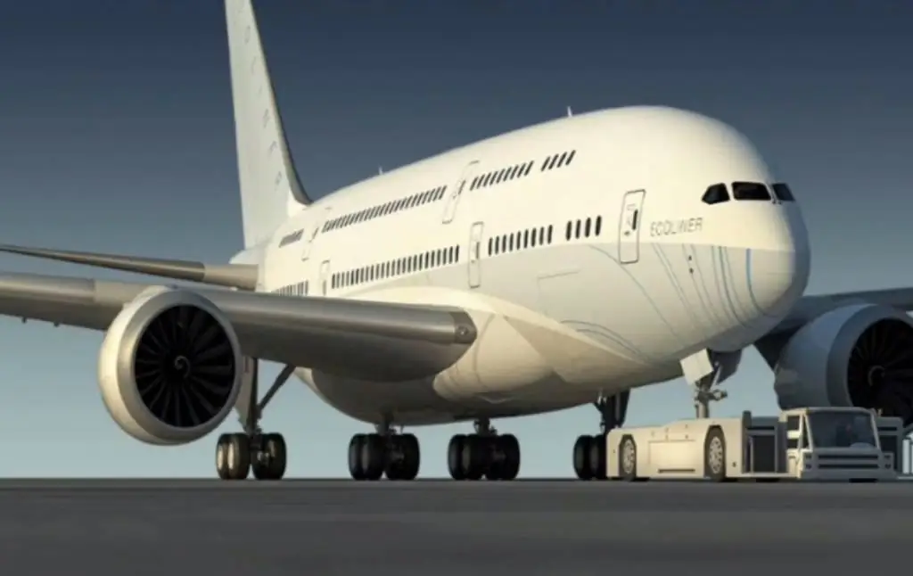
Variety of aircraft, types of their propulsioninstallations and their purpose require a careful approach to the selection of the aircraft wing profile. When designing new aircraft, several alternatives are usually considered. The greater the relative thickness of the wing, the greater the drag. But with thin wings of great length, it is difficult to provide adequate structural strength.
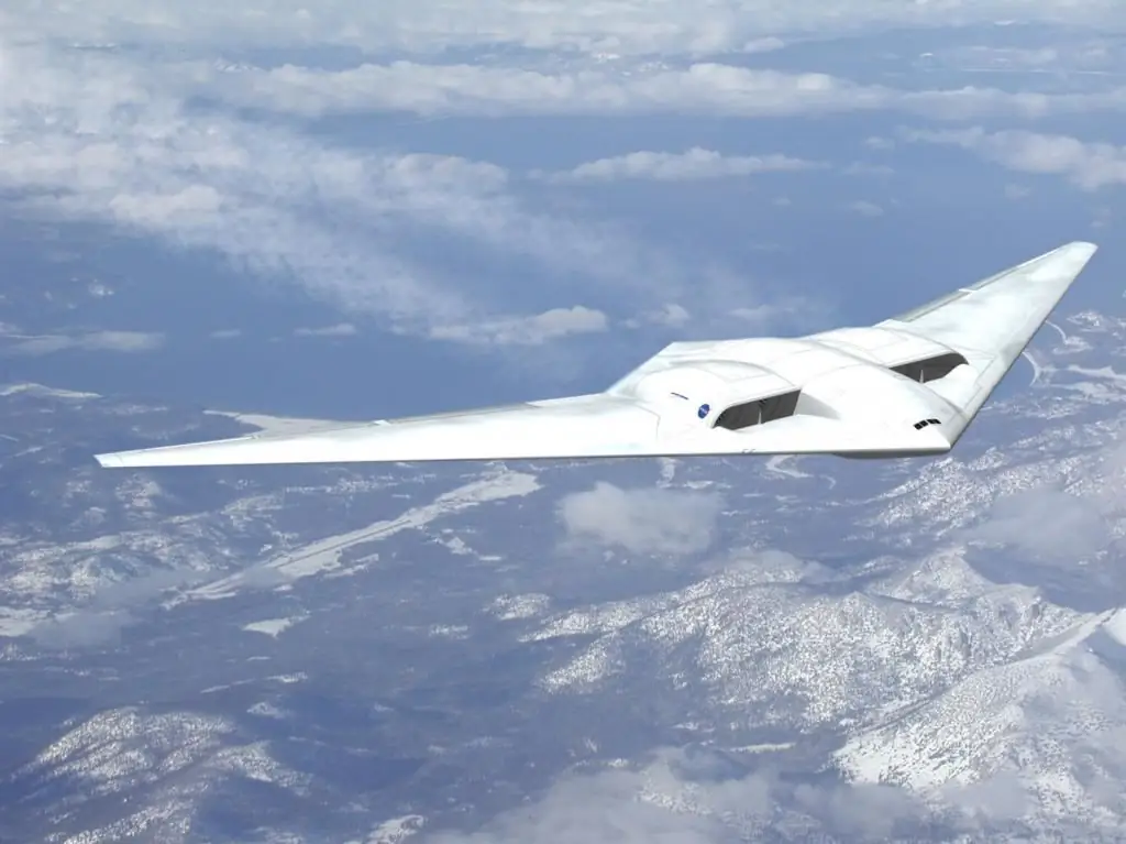
There is a separate question about supersonic machines that require a special approach. It is quite natural that the profile of the wing of the An-2 aircraft ("maize") will differ from the profile of a fighter and a passenger liner. Symmetrical and S-shaped wing profiles create less lift but are more stable, a thin wing with a slight camber is suitable for high-speed sports cars and fighter aircraft, and a thick wing with a large camber, used in large passenger aircraft, can be called the wing with the highest lift. Supersonic aircraft are equipped with wings having a lenticular profile, while diamond-shaped and wedge-shaped profiles are used for hypersonic aircraft. It should be borne in mind that by creating the best profile, you can lose all its advantages only due to poor surface treatment of wing panels or poor aircraft design.
Characteristic calculation method
Recently, calculations of the characteristics of a wing of a certain profile are carried out using computers that are capable of conducting multifactor modeling of the behavior of the wing in different conditions. But the most reliable way is natural tests carried out onspecial stands. Individual "old school" employees may continue to do this manually. The method sounds simply menacing: "full calculation of the wing using integro-differential equations with respect to the unknown circulation." The essence of the method is to represent the circulation of the air flow around the wing in the form of trigonometric series and to search for the coefficients of these series that satisfy the boundary conditions. This work is very laborious and still gives only approximate characteristics of the aircraft wing profile.
Aircraft wing structure
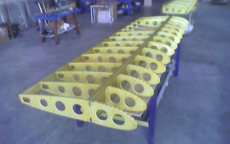
A beautifully drawn and detailed calculated profile must be made in reality. The wing, in addition to performing its main function - creating lift, must perform a number of tasks related to the placement of fuel tanks, various mechanisms, pipelines, electrical harnesses, sensors and much more, which makes it an extremely complex technical object. But speaking very simply, the wing of an aircraft consists of a set of ribs that provide the formation of the desired wing profile, located across the wing, and spars, located along. From above and below this structure is closed with a sheathing of aluminum panels with a stringer set. The ribs along the outer contours fully correspond to the profile of the aircraft wing. The labor intensity of manufacturing the wing reaches 40% of the total labor intensity of manufacturing the entire aircraft.


